The well control system prevents the uncontrolled flow of formation fluids from the wellbore. When the bit penetrates a permeable formation that has a fluid pressure in excess of the hydrostatic pressure exerted by the drilling fluid, formation fluids will begin displacing the drilling fluid from the well. The flow of formation fluids into the well in the presence of drilling fluid is called a kick.
The well-control system enables the driller to
- Detect the kick;
- Close the well at the surface;
- Circulate the well under pressure to remove the formation fl uids and increase the mud density;
- Move the drillstring up and down with the well closed;
- Divert the fl ow away from rig personnel and equipment;
Failure in detecting a kick or a malfunction in the well-control system may result in an uncontrolled flow of formation fl uids into the wellbore. This unwanted fluid production is called a blowout. A blowout is arguably the worst disaster that can occur during drilling operations. Blowouts can cause loss of lives, drilling equipment, the well, much of the oil and gas reserves in the underground reservoir, and can cause damage to the environment. Thus, the well-control system is one of the more important systems on the rig.
Kick detection during drilling operations usually is achieved by use of a pit-volume indicator or a flow indicator. Both devices can detect an increase in the flow of mud returning from the well over that which is being circulated by the pump.
Pit volume indicators usually employ floats in each pit that are connected by means of pneumatic or electrical transducers to a recording device on the rig fl oor. The recording device indicates the volume of all active pits. High- and low-level alarms can be preset to turn on lights and horns when the pit volume increases or decreases signifi cantly. An increase in surface mud volume indicates that formation fluids may be entering the well. A decrease indicates that drilling fluid is being lost to an underground formation.
Mud-flow indicators are used to help detect a kick more quickly. The more commonly used devices are somewhat similar in operation to the pit-level indicators. A paddle-type fluid-level sensor is used in the flowline. In addition, a pump-stroke counter is used to sense the flow rate into the well. A panel on the rig floor displays the flow rate into and out of the well. If the rates are appreciably different, a gain or loss warning will be given.
While making a trip, circulation is stopped and a significant volume of pipe is removed from the hole. Thus, to keep the hole full, mud must be pumped into the hole to replace the volume of pipe removed. Kick detection during tripping operations is accomplished through use of a hole fill-up indicator. The purpose of the fill-up indicator is to measure accurately the mud volume required to fill the hole. If the volume required to fill the hole is less than the volume of pipe removed, a kick may be in progress.
Small trip tanks provide the best means of monitoring hole fill-up volume. Trip tanks usually hold 10 to 15 bbl (1.6 to 2.4 m3) and have 1-bbl (0.16 m3) gauge markers. Periodically, the trip tank is refilled using the mud pump. The required fill-up volume is determined by periodically checking the fluid level in the trip tank. When a trip tank is not installed on the rig, hole fill-up volume should be determined by counting pump strokes each time the hole is filled. The level in one of the active pits should not be used since the active pits are normally too large to provide suffi cient accuracy.
The flow of fluid from the well caused by a kick is stopped by use of well-control devices called blowout preventers (BOPs). The BOP will close the well and hold well pressure, consequently impeding new fluid from entering the wellbore.
Multiple BOPs with different purposes are used in a well. This arrangement is called a BOP stack. The reason for using a BOP stack is to enable the system to close the well and stop the flow of unwanted fluid into the wellbore under all drilling conditions. The well-control system must enable well closure while drilling, tripping in or out of the hole, running casing, and even when there is no drillstring inside the well.
When the drillstring is in the well, movement of the pipe without releasing well pressure should be allowed to occur. In addition, the BOP stack should allow fluid circulation through the well annulus under pressure. These objectives usually are accomplished by using several ram preventers and one annular preventer.
An example of a ram preventer is shown in Fig.1. Ram preventers have two packing elements on opposite sides that close by moving toward each other. Pipe rams have semicircular openings that match the diameter of pipe sizes for which they are designed. Thus, the pipe ram must match the size of pipe currently in use. If more than one size of drillpipe is in the hole, additional ram preventers must be used in the BOP stack. Rams designed to close when no pipe is in the hole are called blind rams. Blind rams will flatten drillpipe if inadvertently closed with the drillstring in the hole but will not stop the flow from the well. Shear rams are blind rams designed to shear the drillstring when closed. This will cause the drillstring to drop in the hole and will stop flow from the well. Shear rams are closed on pipe only when all pipe rams and annular preventers have failed or, in the case of offshore drilling, when an emergency dictates that the drilling vessel must abandon the location. In that case, the blind ram is intentionally activated, and an emergency disconnection is made. Ram preventers are available for working pressures of 2,000, 5,000, 10,000, and 15,000 psi (14,000, 35,000, 70,000, 100,000 kPa).
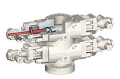
Fig. 1—Double ram preventer (© Cameron 2006).
Annular preventers, sometimes called bag-type preventers, stop flow from the well using a ring of synthetic rubber that contracts around the pipe, preventing fluid passage and sealing the annulus. The rubber packing conforms to the shape of the pipe in the hole. Most annular preventers also will close an open hole if necessary. A cross section of one type of annular preventer is shown in Fig.2. Annular preventers are available for working pressures of 2,000, 5,000, and 10,000 psig (14,000, 35,000, 70,000 kPa).
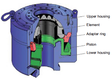
Fig. 2—Annular preventer. Courtesy of National Oilwell Varco.
Both ram and annular BOPs are closed hydraulically. In addition, the ram preventers have a screw-type locking device that can be used to close the preventer if the hydraulic system fails. The annular preventers are designed so that once the rubber element contacts the drillstring, the well pressure helps to hold the preventer closed.
Modern hydraulic systems used for closing BOPs are high-pressure fluid accumulators similar to those developed for aircraft fluid-control systems. The accumulator is capable of supplying sufficient high-pressure fluid to close all of the units in the BOP stack at least once and still have a reserve. Accumulators with fluid capacities of 40, 80, or 120 gal (0.15, 0.30, or 0.45 m3) and maximum operating pressures of 1,500 or 3,000 psig (10,000 or 20,000 kPa) are common. The accumulator is maintained by a small pump at all times, so the operator has the ability to close the well immediately, independent of normal rig power. For safety, standby accumulator pumps are maintained that use a secondary power source.
The accumulator is equipped with a pressure-regulating system. The ability to vary the closing pressure on the preventers is important when it is necessary to strip pipe into the hole. Stripping the pipe means moving the pipe with the preventer closed. A pipe may be stripped either into or out of the well. If a kick is taken during a trip, it is best to strip back to bottom to allow efficient circulation of the formation fluids from the well. The application of too much closing pressure to the preventer during stripping operations causes rapid wear of the sealing element. The usual procedure is to reduce the hydraulic closing pressure during stripping operations until there is a slight leakage of well fluid.
Stripping is accomplished most easily using the annular preventer. However, when the surface well pressure is too great, stripping must be done using two pipe ram preventers placed far enough apart for external-upset tool joints to fit between them. The upper and lower rams must be closed and opened alternately as the tool joints are lowered through.
Space between ram preventers used for stripping operations is provided by a drilling spool. Drilling spools also are used to permit attachment of high-pressure flowlines to a given point in the stack. These high-pressure flowlines make it possible to pump into the annulus or release fluid from the annulus with the BOP closed. A conduit used to pump into the annulus is called a kill line. Conduits used to release fluid from the annulus may include a chokeline, a diverter line, or simply a flowline. All drilling spools must have a large enough bore to permit the next string of casing to be put in place without removing the BOP stack.
The BOP stack is attached to the casing using a casing head. The casing head is welded or connected to the first string of casing cemented in the well. It must provide a pressure seal for subsequent casing strings placed in the well. Also, outlets are provided on the casing head to release any pressure that might accumulate between casing strings.
The control panel for operating the BOP stack usually is placed on the derrick fl oor for easy access by the driller. The controls should be marked clearly and identifiably with the BOP stack arrangement used. Modern and safer rigs will have at least one other control panel located far from the rig floor. This panel will be used in case it is necessary, for safety reasons, to evacuate personnel from the rig floor.
The arrangement of the BOP stack varies considerably. The arrangement used depends on the magnitude of formation pressures in the area and on the type of well-control procedures used by the operator. API presents several recommended arrangements of BOP stacks, including Spec. 16A (2004), Spec. 16C (1993), and Spec. 16D (2004). Fig.3 shows two typical BOP stack arrangements, showing several types of rams, annular preventers, drilling spools, and flowlines. In some cases, it may be desirable to conduct drilling operations with surface pressure on the annulus. A rotating head, which seals around the kelly at the top of the BOP stack, must be used when this is done. Rotating heads most commonly are employed when air or gas is used as a drilling fluid.
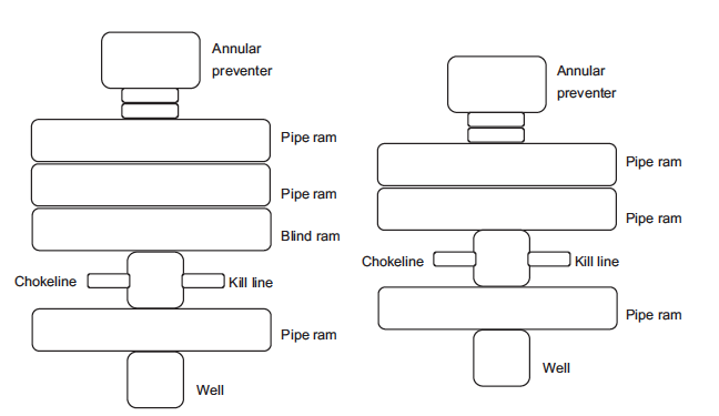
Fig.3—BOP stack arrangements.
When the drillstring is in the hole, the BOP stack can be used to stop only the fl ow from the annulus. Several additional valves can be used to prevent fl ow from inside the drillstring. These valves include kelly cocks (i.e., valves inside the kelly) and inside BOPs. Generally, an upper kelly cock having left-hand threads is placed above the kelly, and a lower kelly cock having right-hand threads is placed below the kelly. The lower kelly cock also is called a drillstem valve. Two kelly cocks are required because the lower position might not be accessible in an emergency if the drillstring is stuck in the hole with the kelly down.
An inside BOP is a valve that can be placed in the drillstring if the well begins flowing during tripping operations. Inside BOPs can use a ball valve or dart-type valve (check valve), as shown in Fig.4. An inside BOP should be placed in the drillstring before drillpipe is stripped back in the hole because it will permit mud to be pumped down the drillstring after reaching the bottom of the well. Inside BOPs are installed when needed by screwing into the top of an open drillstring with the valve or dart in the open position. Once the BOP is installed, the valve can be closed or the dart released.
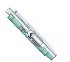
Fig. 4—Inside BOP with dart-type valve (National Oilwell Varco 2010b).
A high-pressure circulating system is used for well-control operations. The kick normally is circulated from the well through an adjustable choke. The adjustable choke is controlled from a remote panel on the rig floor. Sufficient pressure must be held against the well by the choke so that the bottomhole pressure in the well is maintained slightly above the formation pressure. Otherwise, formation fluids would continue to enter the well.
Mechanical stresses on the emergency high-pressure flow system can be quite severe when handling a kick. The rapid release of large volumes of fluid through the surface piping frequently is accompanied by extreme vibrational stresses. Thus, care should be taken to use the strongest available pipe and to anchor all lines securely against reaction thrust. Also, some flexibility in the piping to and from the wellhead is required. The weight of all valves and fittings should be supported on structural members so that bending stresses are not created in the piping.
Because of fluid abrasion, the number of bends should be minimized. The bends required should be sweepturn bends rather than sharp “L” turns, or should have an abrasion-resistant target at the point of fluid impingement in the bend.
API has several recommended choke manifold arrangements for 2,000-, 3,000-, 5,000-, 10,000-, and 15,000- psi (14,000, 21,000, 34,000, 69,000, and 100,000 kPa) working pressure systems (Spec. 16C 1993). In addition to these recommendations, well operators have developed many other, optional designs.

%20(1).png)


