Drilling wells offshore, from a floating vessel, requires special equipment and procedures. Even though the drilling operation itself is similar to onshore drilling, special equipment is required to hold the vessel on location over the borehole and to compensate for the vertical, lateral, and tilting movements caused by wave action against the vessel.
In the past, most floating vessels were held on location by anchors. However, to anchor a drillship or a semisubmersible in deep water using conventional anchors and cables or chains is virtually impossible. Consider an operation at a water depth of 2000 m (6,560 ft). The cables or chains connecting the anchor with the vessel would have to be huge in order to support the large tensions. Consequently, the vessel space required to store the cables must also be very large. Further, the operation to position the anchors would be very difficult, probably unfeasible. Even though there are some reports (Maksoud 2002) of deepwater mooring, this was achieved with special cables made of polyester and a mooring system that used a special suction anchor system. This system needs the support of other boats to handle the anchors and cables. On the other hand, a dynamically positioned drillship can move to the location and get positioned using only its own equipment; no additional support is needed.
Conventional anchored vessels are limited to just a few hundred meters of water depth. When the ocean bottom is too hard for conventional anchors, anchor piles are driven or cemented in boreholes in the ocean floor. The vessel is moored facing the direction from which the most severe weather is anticipated. Certain drillships are designed to be moored from a central turret containing the drilling rig. In this case, the ship will rotate about the turret so that it always faces incoming waves. Most mooring systems are designed to restrict horizontal vessel movement to approximately 10% of the water depth for the most severe weather conditions; however, horizontal movement can be restricted to approximately 3% of the water depth for the weather conditions experienced 95% of the time. As many as 12 anchors are used in a mooring system. For anchored vessels, motion problems are more severe for drillships than for semisubmersibles. However, drillships usually are easily operated and can be moved rapidly from one location to the next.
For deep and ultradeep water, where anchoring systems are not feasible, an anchorless system was developed. In this case, the vessel has large thrusters (Fig. 1), units capable of holding the drilling vessel on location without anchors. This system is called dynamic positioning (DP), and it works to counteract the forces to which the drilling vessel is subjected while on location. The wind, waves, and maritime currents will tend to displace the vessel from its station. Sensors at the vessel detect these actions and require the thrusters to counteract the forces accurately. The entire system is controlled by two independent computer systems. In addition, manual position and heading control is also available. Table 1 shows the classifi cation of DP systems according to standards established by the International Maritime Organization (IMO). Fig. 2 shows a DP control room, and Fig.3 shows a diagram of the basic elements of a DP system.
Even though DP systems are designed mainly for use in water depths in excess of 700 m (2,300 ft), there are cases in which DP vessels (semisubmersibles or drillships) have been used in lesser depths due to their practicality and time-saving capability.
A special derrick design must be used for drillships because of the tilting motion caused by wave action. The derrick of a drillship often is designed to withstand as much as a 20° tilt with a full load of drillpipes standing in the derrick. Also, special pipe-handling equipment is necessary to permit tripping operations to be made safely during rough weather. This equipment permits drillpipe to be laid down quickly on a pipe rack in doubles or
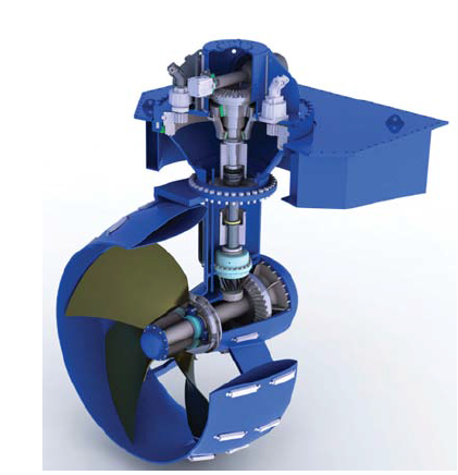
Fig.1—Thruster with controllable-pitch propeller (Thrustmaster of Texas 2010).

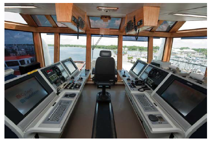
Fig. 2—DP control room. Courtesy of Keith Wyatt, Converteam.
triples rather than supported in the derrick. A block guide track also is used to prevent the traveling block from swinging in rough weather.
Normally, in marine operations from floating vessels, the wellhead and BOPs are placed at the seafloor. A marine riser conducts the drilling fluid from the ocean floor to the drilling vessel. A flex joint at the bottom of the marine riser allows lateral movement of the vessel. The vertical movement of the vessel is allowed by a slip joint placed at the top of the marine riser. The riser is secured to the vessel by a pneumatic tensioning system. To reduce tension requirements in long and heavy riser strings, buoyant sections made of light material are added to the riser system.
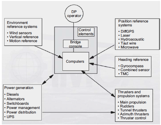
Fig. 3—The elements of a DP system (IMCA 2003). Courtesy of the International Marine Contractor Association.
To keep the drillstring from suffering the effects of the vertical movement of the vessel and to keep the weight on bit constant, types of surface-motion-compensating equipment called heave compensators have been developed. A constant hookload is maintained through use of a pneumatic tensioning device on the traveling block. As mentioned before, the BOP stack for a fl oating drilling operation normally is placed on the ocean fl oor below the marine riser. However, in recent years, alternatively, a system with a slim high-pressure riser system and a surface BOP has been developed. Even though a subsea BOP could be considered the standard drilling procedure, a number of wells (DeLuca 2005) have been drilled lately using surface BOPs.
The subsea BOP ensures that the well can be closed even in severe weather, such as a hurricane. In such extreme conditions, the BOP can be closed and the marine riser disconnected from the top of the BOP system, allowing the vessel to go to a safer place. Later, when weather conditions get back to normal, the vessel returns to the location and the riser is reconnected to the BOP so that the operation can resume. If the drillstring is in the well and an emergency disconnection is necessary, the BOP’s shear ram is used to cut off the drillpipe. Then, the BOP’s blind ram also is closed, keeping the well shut. Later, after the reconnection, the portion of the drillstring remaining in the well can be fished (special tools are used to retrieve the original drillpipe), the damaged pipe substituted, and the operation resumed.
Another feature of the subsea system is that identical hydraulically operated connectors often are used above and below the BOP stack. This makes it possible to add on an additional BOP stack above the existing one in an emergency.
Offshore drilling operations differ from onshore drilling in various aspects, including well spud-in (initiating a well), in which the differences in equipment and operating procedures are considerable. For drilling operations from floating vessels, this difference is even more significant. Various schemes have been developed for offshore well spud-in. To illustrate those differences, let us analyze initial drilling operations for a shallow-water well drilled from a jackup rig and a deepwater well drilled from a floating DP vessel. Note that the sequence of operations presented for both cases does not represent the only possible way to initiate a well because these operations can vary depending on the type of rig and equipment used.
In a jackup rig, the fi rst section may be drilled using, for example, a 26-in. bit coupled with a 36-in. hole opener. This fi rst section normally is not long, and when concluded, a 30-in. conductor is run into the well and cemented. The 30-in. conductor (Fig. 4) has an internal profi le that allows support, at mudline, for the next casing, normally a 20-in. surface casing. Alternatively, the conductor could be jetted instead of cemented. In the case of jetting, the initial well section is drilled by the action of water jets positioned at the lower end of the conductor. When the planned depth is reached, the conductor is already in place.
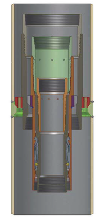
Fig. 4—MLH Mud Line Suspension System (photo courtesy of GE Oil & Gas).
After this first phase is concluded, the conductor is cut below the rotary table, and the first wellhead and a diverter is installed at its top so that the drilling operation can resume. The next section is drilled using, for example, a 26-in. bit, and afterward a 20-in. casing will be run and cemented. Note that this casing has its weight supported by the 30-in. conductor at mudline, avoiding unnecessary loads to the rig.
The 20-in. casing, when cemented in place, also is cut below the rotary table, allowing a wellhead and BOP to be installed on its top. After that, drilling operation resumes, with each section being drilled and its associated casing being run and cemented in a similar fashion. Normally, the first low-pressure BOP, installed on top of the 20-in. casing, is changed after the next casing is run, so that high-pressure safety equipment can be installed. Note that, because all safety and wellhead equipment is installed at surface, subsequent operations are quite similar to onshore drilling.
When drilling from a floating vessel, normally the wellhead and BOPs are installed close to seafl oor and are called a subsea system. There are many different wellhead and subsea BOP confi gurations. One type of design, which has been in use since the early 1980s, involves the installation at seafloor of two guide bases. The first one, called the temporary guide base, is a heavy steel structure with an opening in the center and four cables, called guidelines, surrounding the central hole and extending back to the vessel, where a constant tension is maintained in the cables.
With the temporary base in position, a drillstring with the first drill bit is lowered to the seafloor, and the first section of the well is drilled. Commonly, a remotely operated vehicle (ROV) is used to monitor the operation. The ROV has a camera that transmits the view of the action to a monitoring station located at surface on the drilling vessel.
After conclusion of drilling, the first casing is run into the well with the permanent guide base attached to its top, and, as the casing is placed in position, the permanent guide base is landed on the temporary base (Fig.5).
After the first well section is concluded, a second section is drilled, also without a BOP system. A marine riser may be installed in the wellhead housing of the previous casing; if so, a diverter system is installed at surface to deal with the possible hazards associated with drilling into shallow gas zones. This will allow formation fluids to be diverted away from the rig in an emergency.
After drilling, the conductor casing is lowered into the hole with a high-pressure subsea wellhead housing attached to its top. The wellhead housing internal profi le (see Fig.5) is designed to receive subsequent casing strings. The BOP stack is lowered and latched into the top of the wellhead, and the marine riser then can be deployed and latched into the BOP.
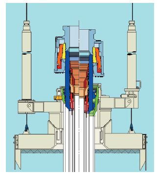
Fig.5—SS10 subsea system with temporary and permanent guide base (courtesy of Dril-Quip).
As can be seen from the above sequence of operations, well startup from a fl oating vessel can be very timeconsuming, which directly affects well cost because daily rates for fl oating vessels tend to be especially high. This situation is more noticeable for deepwater drilling, where the tripping operations to install subsea equipment at seafl oor take even longer.
Recently, modern subsea systems and procedures were specially developed for deepwater drilling. These systems allow the operator, in one trip, to run the fi rst large-bore casing and its wellhead housing and, after jetting it in place, to immediately start drilling the second well section without tripping back to surface. The sequence of operation for deepwater well spud-in is as follows (see Fig.6):
- Run the conductor and its wellhead housing and jet it in place.
- Release the running tool and drill ahead with the bit and BHA previously connected with the running string and positioned inside the conductor.
- After conclusion of drilling, retrieve the drillstring and the running tool to surface.
- Run the next casing with the high-pressure wellhead. The casing is run with a running tool connected to the wellhead, and casing length is calculated so that, when the casing shoe is in place, the wellhead is landed on the wellhead housing. After landing the wellhead, cement the casing and then retrieve the running tool and running string back to surface.
- Run the BOP with the riser already connected on its top. The BOP is then landed on the high-pressure wellhead.
- With the BOP and riser in place, the operation to drill the next section can be carried out.
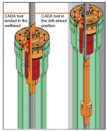
Fig.6—Cam-actuated drill-ahead (CADA) tool (courtesy of Dril-Quip).

%20(1).png)

