Casing comes in odd assortment of diameters ranging from 4.-in. to 20-in. that may seem quite puzzling at first encounter, such as 5.-in., 7-in., 7⅝-in., 9⅝-in., 10.-in. Why such odd sizes? All we can really say about that is that they stem from historical sizes from so far back that no one knows the reasons for the particular sizes any longer. Some sizes became standard and some vanished. Within the different sizes, there are also different wall thicknesses. These different diameters and wall thicknesses were eventually standardized by the API (and now ISO). The standard sizes as well as dimensional tolerances are set outin API Specification 5CT (2001) and ISO 11960 (2004).
Outside Diameter
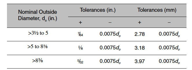
The size of casing is expressed as a nominal diameter, meaning that is the designated or theoretical diameter of the pipe. API and ISO allow for some tolerance in that measurement, and the specific tolerance differs for different size pipe. The tolerance for the pipe being under sized is typically less than for the pipe being oversized. This is to ensure that the threads cut in the pipe are full threads. The tolerances for non-upset casing 4. in. and larger are given as fractions of the outside diameter, +0.01do, –0.005do. For upset casing, Table 1–1 shows the current API and ISO tolerances measured 5 in. or 127 mm behind the upset.
Table 1–1 API/ISO Tolerances for Upset Casing Outside Diameter (API 5CT, ISO 11960)


Inside Diameter and Wall Thickness
The inside diameter of the casing determines the wall thickness or vice versa. Rather than a specific tolerance for the amount at which the internal diameter might exceed a nominal value, the tolerance specified by API and ISO is given in terms of minimum wall thickness. The minimum wall thickness is 87.5% of the nominal wall thickness. The maximum wall thickness is given in terms of the nominal internal diameter, however. It specifies the smallest diameter and length of a cylindrical drift mandrel that must pass through the casing (see Table 1–2).
The internal diameter of casing is a critical dimension. It determines what tools and so forth may be run through the casing. It is not uncommon to have to select a casing for a particular application such that the drift diameter is less than the diameter of the bit normally used with that size casing, even though the bit diameter is less than the nominal internal diameter of the pipe. In cases like this, it is a practice to drift the casing for the actual bit size rather than the standard drift mandrel. This may be done with existing pipe in inventory, and those joints that will not pass the bit are culled from the proposed string. Or it may be done at special request at the steel mill, in which case there will be an extra cost. This procedure applies only to casing where the desired bit diameter falls between the nominal internal diameter and the drift diameter of the casing.

%20(1).png)


